Xiao Daughter Board -> Xiao Module
Solder wires between J1, J2, J3, J4, J5, J6, J7 & J9 of the daughter board to the respective solder tags on the Xiao module. The holes roughly align but will be at a small angle with respect to the boards. As the KiCAD drawing above depicts, the connections are:
J1 - D10
J2 - 5V
J3 - Batt+ Note: An insulated wire needs to pass through the Xiao D2 solder hole to the back of the Xiao
J4 - D1
J5 - SCL
J6 - SDA
J7 - 3V3
J9 - GND
Sensors Soldered Together with Flying Wires
( +, - , SDA , SCA to Daughter Board)
Use double-sided tape to attach the DPS310 PCB to the SDP31 PCB.
3D Print a soldering jig from the Onshape drawing here: Onshape Nose_Jig
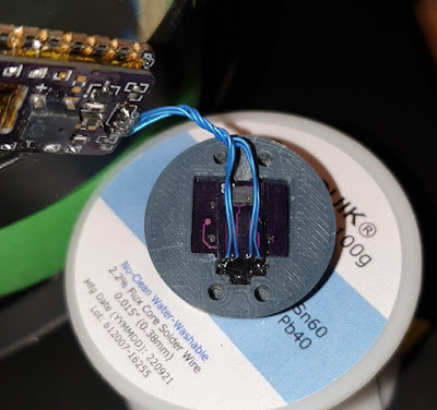
Insert the boards and run wires like this:
With all 4 wires run, solder them and trim the wire-ends at the SHT45 PCB:
For testing outside an enclosure - the wires connect from the Sensor-PCBs to the Xiao Daughter Board 1 to 1. Be sure to start at GND, which is a square solder hole (the other three are round):
If installing into the Onshape 3D printed enclosure, insert the Xiao|Daughter Board combo into the middle section of the probe enclosure:
Here is how the PCB's slot into the nose section:
UPDATE August 2023
I found the RF-can of the Xiao board could easily short out connections if not carefully insulated. Therefore I am now insulating the can with Polyimide (Kapton) tape. Picture:
Now is a good time to solder-connect the sensors to make sure all is working:
Here is current draw in normal operation (BT connection established & transmitting data):
Prepare the slide switch by soldering wires and heatshrink covering:
Note the air-gap above the Temp/Hum sensor. This needs to be filled so the enclosure does not pressurise and affect the barometric sensor (thank you Bernd from TotalVario!). I use Star brite liquid electrical tape:
Fill the aforementioned gap and allow to cure:
Before assembling there are two new tasks I had not anticipated (again thanks Bernd).
The first is to add pitot-like static pressure holes. I have created a jig on Onshape for this. The holes are 0.5mm and there are four of them (just like the static-pressure pitot tube)
.The second is to add Xiao reset connections if wanting to re-program the Xiao. Otherwise, disassembly may be required. There is also a jig for this on Onshape.
.The second is to add Xiao reset connections if wanting to re-program the Xiao. Otherwise, disassembly may be required. There is also a jig for this on Onshape.
I used the pins of an IC socket (machined type, not folded):
Power ON via the slide switch. You should hear the startup tones. Connect to BT on your phone and you should then hear a short 'connection successful tone'.
Test with TotalVario.
Programming
To finish, here is a reset push-button switch connected:
To finish, here is a reset push-button switch connected:


